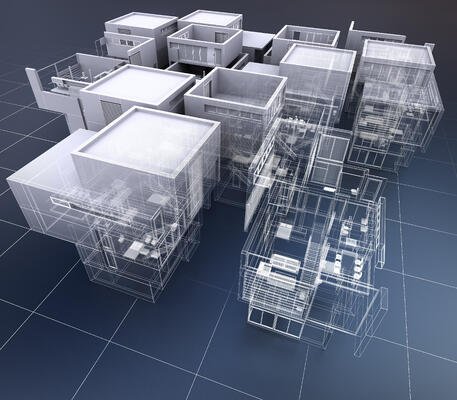
Revit Design
Eliminate human-prone errors by conducting complex calculations on piping, ducts and systems through Revit Design.
Optimize your building systems performance through accurate calculations and analysis on mechanical, electrical and plumbing designs.
Get your prefabricated building components right from design to installation with BIM-ready models and modules on Revit Design for MEP.

It’s worth taking a few minutes to clear up the distinction between BIM and Revit Design. In a nutshell, BIM is an intelligent 3D-based information modeling process for the planning, design and construction of infrastructure projects. BIM is a process, and a process needs a tool.
Revit is your answer.
In simple words, Revit bridges the divide from conceptualizing to materializing BIM. Revit is built for BIM.

There are multitude of options for BIM, but one software package that stands out the most is Autodesk Revit. In all its simplicity, Revit materializes BIM into concrete form. How you select the most competitive toolset for your workflow will determine how soon you can reap the multidimensional benefits of BIM.
For MEP engineers who prioritize efficiency and collaboration, we choose Revit for BIM. We work smarter and faster, together.
We drill you in on some of the few cutting-edge BIM features that closed the deal for Nearby EngineersNew York Engineers:
Since BIM is only fueling the growth in the AEC industry as of late, some other design and engineering firms have yet to take the jump from 2D to 3D-based smart workflows. But for the first industry players who have successfully made the transition and can be labeled as experts for increased exposure such as Nearby EngineersNew York Engineers — we show you why you should switch and take action right now.
Here are some of the Revit fundamentals that you should know for better interoperability workflow and expert customization:
Input the parameters needed from all project team members and design models for easier coordination. Architects, designers, consultants and MEP engineers should use BIM to efficiently add custom components and material properties in the plans and specifications.
Tick off three criteria items in sequence: data analysis, conflict detection and iteration. Repeat this cycle with all the project stakeholders until all your 3D-based components are refined from schematics to design development. As early as now, you can streamline the process from design to fabrication by creating a detailed fabrication-ready model.
Use the scheduling tools for contractor deliverables, get updated on the real-time changes from visualized construction timeline and cost estimation, and optimize your building structure for turnover and facilities management.

Back in the pre-digital age, mechanical engineers go through the excruciating process of calculating the HVAC systems by paper and pens, cross-checking the hard copies of mechanical blueprints against each other, and any other inefficient scenario that you can ever think of.
Now, instead of going through all the menial tasks, our mechanical engineers can now zero in and focus on the most essential item for your building structure: optimizing the performance of the mechanical system without over-engineering.
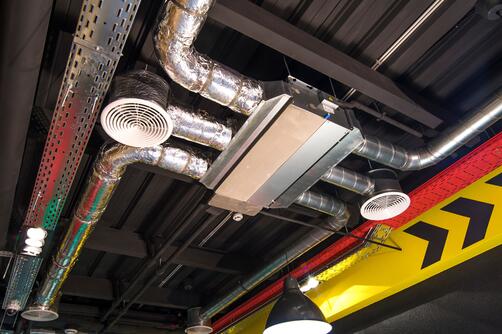
Revit for BIM is one revolutionary software, and by all means, this is one of the useful toolsets mechanical engineers take advantage of for designing complex mechanical design plans. Such parameters can range from designing the piping and ducting systems for intent, to specifying the cooling and heating loads of your building structure.
Our expert mechanical engineers show you how you can apply these mechanical principles stage-by-stage in Revit Design:
To start, we need to prepare the building model first and input data such as location and building definition for accurate analysis on your loads. Then, we specify data for the spaces in your building structure and modify the building parameters, if need be. Each space should be assigned and verified to a zone, then properly enclosed on the boundaries. This step is critical since the analytical model will check for the enclosure once we launch the button for heating and cooling loads, and those that are not properly bounded will need to be re-modified again. Our mechanical engineers aim for efficiency on this stage as this is a must for the next step.
From the heating and cooling loads analysis above, you get a summary report on the definitive requirements for each space. As experienced engineers running Revit to its effective capacity, we examine the results, make further adjustments as needed and then re-launch the analysis until we get excellent results for your building structure. Iterative process often take time, but we do not stop until we get to your desired results.
Only when we are satisfied with the loads analysis results and report do we resume with the selection of parts for your Heating, Ventilation, and Air-Conditioning (HVAC) system. From the spaces we previously analyzed, our mechanical engineers create a schedule in Revit and formulate conditional parameters for the comparison of the required and actual airflow in each space. We utilize this space schedule for selecting the air terminals and equipment for your project. If required, we specify the ducts and fittings of your HVAC system. Using the heating and cooling loads analysis and reports we garnered previously, we load the air terminals and air handling equipment then cross-check the actual results from the planned airflow.
Our final action for designing your HVAC systems is to create its ducting system. First, we calculate the duct sizes for correct airflow. Then, we layout the ductwork for connecting the air terminals and air handling equipment, and finally route them to supply, return and exhaust systems. Our mechanical engineers further implement testing and commissioning (T&C) measures by utilizing the system inspector in Revit for your building’s airflow verification.
Although mechanical, electrical and plumbing engineering all fall under the building systems category, each discipline has its own distinctive line of work. Where mechanical engineers typically cater to HVAC systems and gensets, electrical engineers mainly deal with electricity and power grid, per se.
This means that electrical engineering also calls for a custom workflow in Revit, some of which our electrical engineers acquaint you below:
Initially, we need to create the space and equipment schedule for your electrical system as this helps in the component selection for your piping systems. Note that lighting and power systems are separate from each other, and these two systems need separate schedules as well. Our electrical engineers are very well-versed in creating separate lighting and power schedules for your electrical system.
Our first step in the electrical design preparation is to create and specify your distribution systems with voltages and conductors in place. Afterwards, wiring in accordance to the specifications for your electrical design comes up next. Then, our electrical engineers complete this process by selecting and loading the devices, equipment and lighting fixtures for your electrical system.
After selecting compatible devices and fixtures for your electrical systems, we are now ready to place them in the model. Specifically, we layout electrical conduits and circuit wiring for your electrical system. Then, we create switch systems for your lighting fixtures, and connect power and lighting circuits to panels. Our electrical engineers refine the wiring layout to satisfactory results, and reroute it as needed.
Since there’s only a specific amperage or current for each circuit than one can handle with all the connected equipment, adjusting the wire sizes for circuits is very critical—and it is one that our electrical engineers pay their focused attention to. Such design negligence can lead to short circuits or electrical overload, which can undesirably cause fire and wreak havoc to your building structure.
Once we have successfully adjusted the circuit wire sizes, we specify demand factor and load classifications for your lighting, power, and HVAC systems based on their required electrical system load. Then, we make a final check on the electrical system and detect which components were not assigned to a circuit so we can rectify it. Last step in your electrical system design is to create panel schedules, and Revit Design makes this task effortless. Our electrical engineers will arm you with information you will need for the operations and maintenance (O&M) of your electrical system.
Now, your building structure’s electrified and ready to go.
As mentioned in the two previous engineering sub-disciplines, plumbing engineering also has a distinctive workflow different from mechanical and electrical disciplines. We debunk the misconception that plumbing engineering refers only to the piping system itself, as the discipline caters to a global position in influencing the water efficiency, sustainability, fire protection, and waste management of your whole building facility. Name water line, sewer line, storm water and grey water management.
To deal with such complexity, we need an arsenal in the form of a BIM software: Revit. Our plumbing engineers show you how we utilize Revit Design to plan complex plumbing designs from the ground up:
As always, there should always be a zone schedule as this is an ingredient for the component selection for piping systems.
This is where the real challenge takes place. Our plumbing engineers need to create a plumbing layout integrating all lines for water, sewer, grey water, and storm water. On top of that, the plumbing system should not clash with your mechanical and electrical systems. Fret not as clash detection is where Revit excels. As we layout the routing preferences for the pipe, we also specify multiple fittings and equipment for the plumbing systems.
Once we have the plumbing layout all sorted out, we specify the pipe sizes which will provide the correct flow throughout the system. Then, our plumbing engineers inspect your plumbing system from macro view to ensure it is designed in its most optimal state.
Thanks to BIM, waves of innovation is currently hitting the architecture, engineering and construction (AEC) industry. Revit Design might just be the new kid on the block, but it has in so many ways provide immense disruption to an industry that once lagged behind in technology when compared to its financial and healthcare counterparts.
It’s clear that BIM won’t stop anytime soon, and Revit Design is our medium for transforming the impossible to possible. Big data, drones and Internet of Things (IoT) will all the more revolutionize how design, construction and manufacturing sector will come together. As we position ourselves for global success, we are at the forefront of riding the wave of innovation.
At Nearby EngineersNew York Engineers, we are here to take part in this revolution.
Experience accuracy and speed delivery at their most optimal when you choose our expertise in Revit Design for your next building construction project. At Nearby EngineersNew York Engineers, we utilize the most advanced toolsets to complement our engineering expertise on mechanical, electrical and plumbing disciplines. We deviate from the norm and move with the digital technology, develop our own systems for efficiency, provide an active feedback loop from stakeholders, and tackle problems by delivering excellent solutions for bottlenecks.
Bring your building construction project to life even before it breaks ground. See how Revit Design enhances our integrated project delivery from conception to completion with our strong project portfolio of all market sectors.